ESP32移植Openharmony外设篇(2)HCSR501人体感应传感器
HC-SR501是基于红外线技术的自动控制模块,采用德国原装进口 LHI778 探头设计,灵敏度高,可靠性强,超低电压工作模式,广泛应用于各类自动感应电器设备,尤其是干电池供电的自动控制产品。
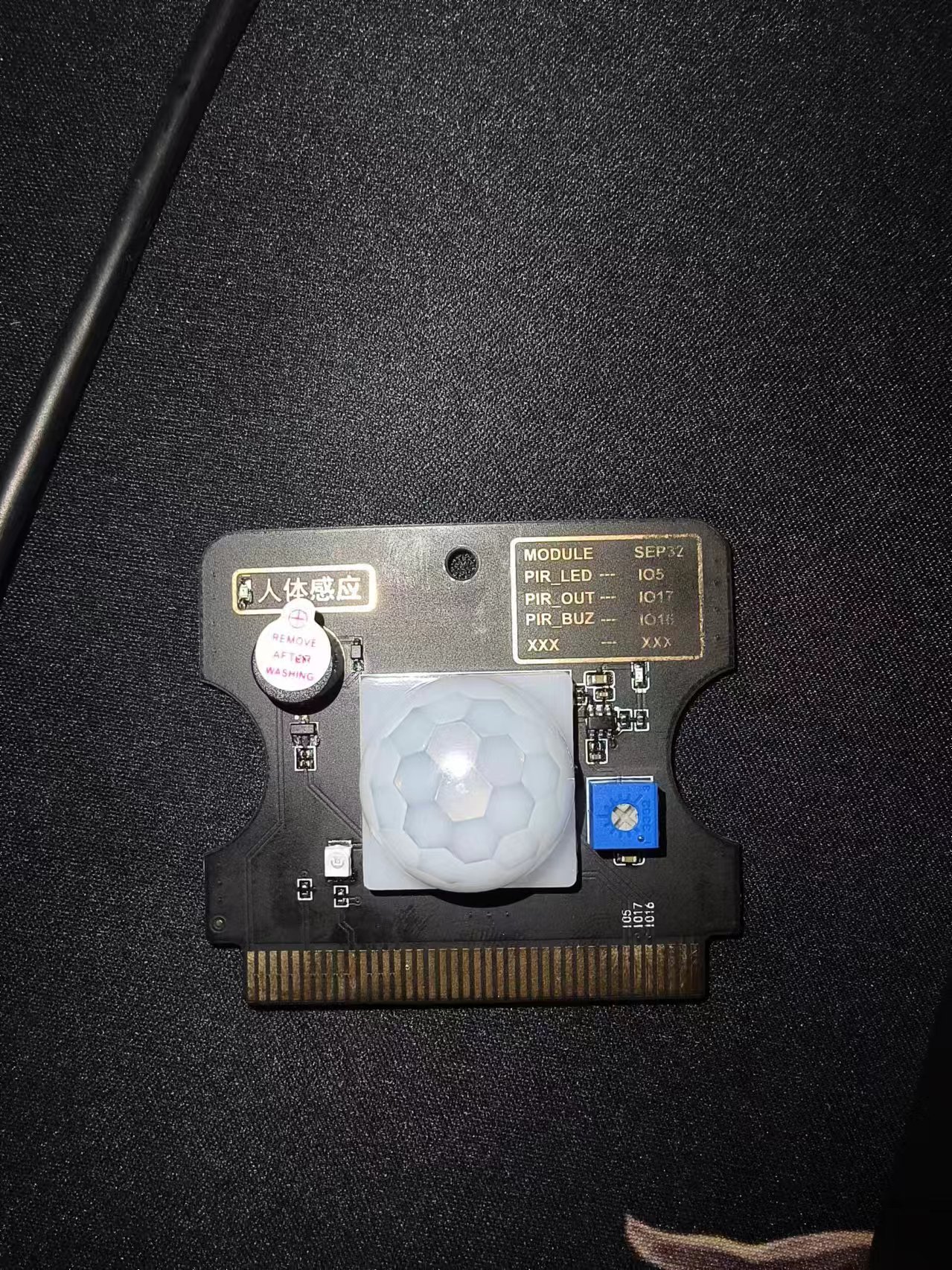
HCSR501人体感应传感器
模块简介
HC-SR501是基于红外线技术的自动控制模块,采用德国原装进口 LHI778 探头设计,灵敏度高,可靠性强,超低电压工作模式,广泛应用于各类自动感应电器设备,尤其是干电池供电的自动控制产品。
传感器特性
1、HC-SR501是基于红外线HC-SR501是基于红外线技术的自动控制模块 ,采用德国原装进口LHI778 探头设计,灵敏度高,可靠性强,超低电压工作模式 ,广泛应用于各类自动感应电器设备 ,尤其是干电池供电的自动控制产品。
2、模块为全自动感应,当人进入其感应范围则输出高电平,人离开感应范围则自动延时关闭高电平,输出低电平。传感器有两种触发方式(可通过跳线进行选择):第一种不可重复触发方式,即感应输出高电平后,延时一段时间结束,输出将自动从高电平变成低电平。第二种可重复触发方式,即感应输出高电平后,在延时时间段内,如果有人体在其感应范围活动,其输出将一直保持高电平,直到人离开后才延时将高电平变为低电平(感应模块检测到人体的每一次活动后会自动顺延一个延时时间段,并且以最后一次活动的时间为延时时间的起始点)
3、具有感应封锁时间(默认设置:2.5S 封锁时间):感应模块在每一次感应输出后(高电平变成低电平),可以紧跟着设置一个封锁时间段,在此时间段内感应器不接受任何感应信号。此功能可以实现“感应输出时间”和“封锁时间”两者的间隔工作,可应用于间隔探测产品;同时此功能可有效抑制负载切换过程中产生的各种干扰。(此时间可设置在零点几秒—几十秒钟)。感应模块通电后有一分钟左右的初始化时间,在此期间模块会间隔地输出0-3 次,一分钟后进入待机状态。
电气参数
|
产品型号 |
HC--SR501人体感应模块 |
|
工作电压范围 |
直流电压4.5-20V |
|
静态电流 |
<50uA |
|
电平输出 |
高3.3V/低0V |
|
触发方式 |
L不可重复触发/H重复 |
|
延时时间 |
2.5s(默认) |
|
电路板外形尺寸 |
32mm*24mm |
|
感应角度 |
<100°锥角 |
|
工作温度 |
-15°~+70° |
|
感应透镜尺寸 |
直径23mm(默认) |
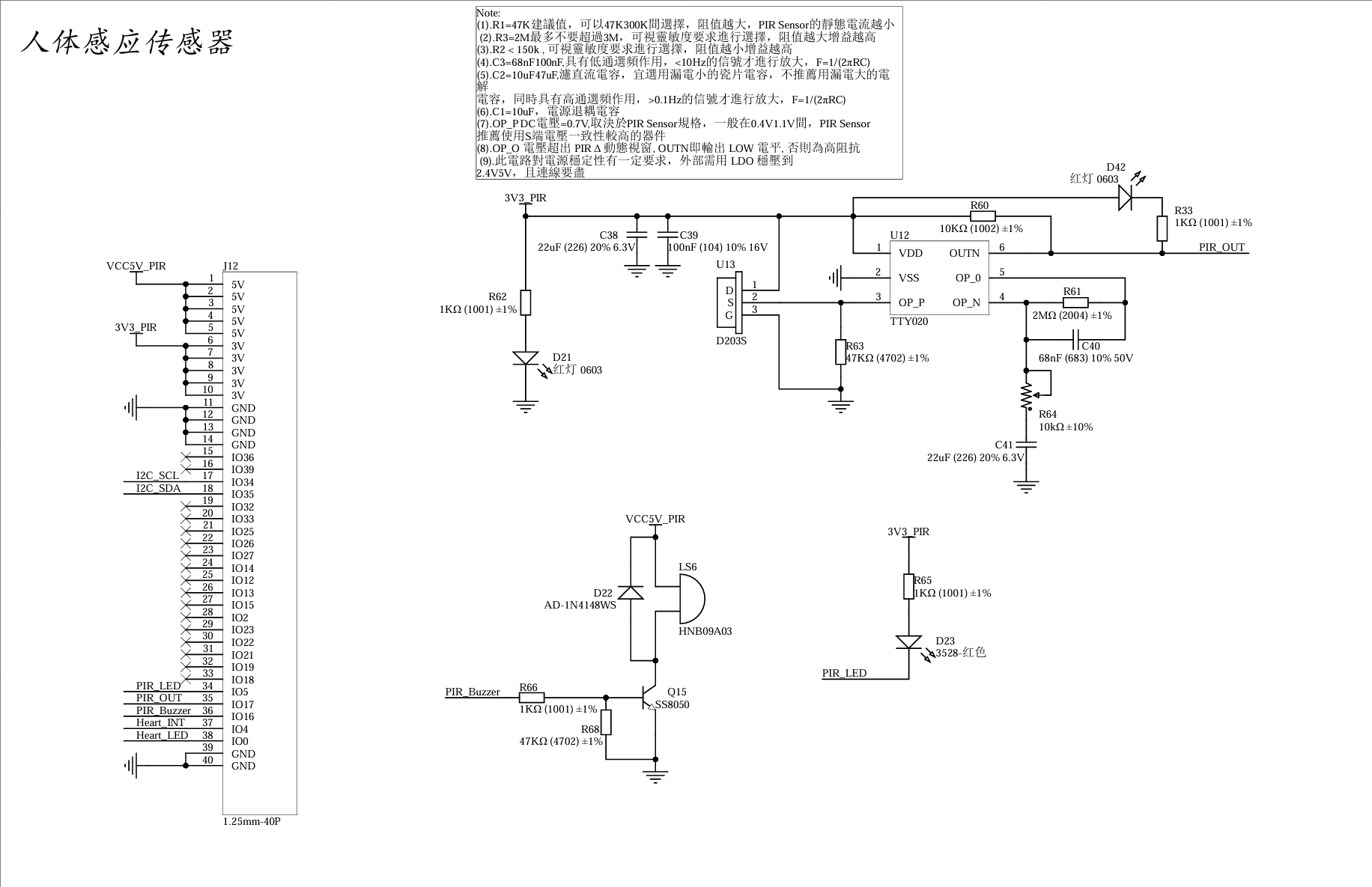
原理图
参考代码
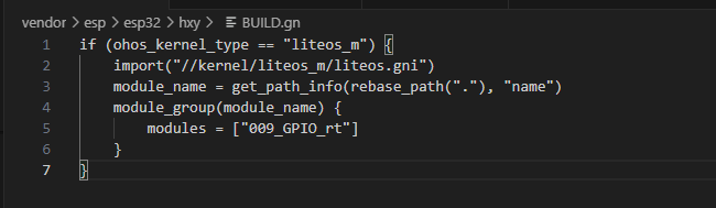
BUILD.gn
# Copyright (c) 2022 Hunan OpenValley Digital Industry Development Co., Ltd.
# Licensed under the Apache License, Version 2.0 (the "License");
# you may not use this file except in compliance with the License.
# You may obtain a copy of the License at
#
#     http://www.apache.org/licenses/LICENSE-2.0
#
# Unless required by applicable law or agreed to in writing, software
# distributed under the License is distributed on an "AS IS" BASIS,
# WITHOUT WARRANTIES OR CONDITIONS OF ANY KIND, either express or implied.
# See the License for the specific language governing permissions and
# limitations under the License.

import("//kernel/liteos_m/liteos.gni")
module_name = get_path_info(rebase_path("."), "name")
kernel_module(module_name){
    sources = [
        "gpio_rt_example.c",
    ]
    include_dirs = [
        "//drivers/hdf_core/framework/include/platform/",
        "//drivers/hdf_core/framework/include/utils/",
        "//drivers/hdf_core/framework/support/platform/include/gpio",
        "//drivers/hdf_core/adapter/khdf/liteos_m/osal/include/",
        "//drivers/hdf_core/framework/include/core/",
        "//drivers/hdf_core/framework/include/osal/",
        "//device/soc/esp/esp32/components/driver/include",
        "//device/soc/esp/esp32/components/esp_adc_cal/include",
        "//device/soc/esp/esp32/components/driver/esp32/include",
    ]
}
gpio_rt_example
#include <stdio.h>
#include "cmsis_os2.h"
#include "ohos_run.h"
#include "esp_system.h"
#include "nvs_flash.h"
#include "esp_log.h"
#include "driver/gpio.h"


#define SYS_DELAY_TICKS 200
#define TASK_STACK_SIZE 4096
#define TASK_PRIO 25


//配置引脚
#define GPIO_RT    GPIO_NUM_17
#define GPIO_BUZ   GPIO_NUM_16

void gpio_init(void)
{
    //配置GPIO为输入
    gpio_config_t gpio_out = {
        .intr_type=GPIO_INTR_DISABLE,
        .mode=GPIO_MODE_INPUT,
        .pin_bit_mask = 1ULL << GPIO_RT,
        .pull_down_en = GPIO_PULLDOWN_ENABLE,
        .pull_up_en =GPIO_PULLUP_DISABLE
    };

    gpio_config(&gpio_out);

    //配置为输出
    gpio_config_t gpio_buz = {
        .intr_type = GPIO_INTR_DISABLE, //关闭中断
        .mode = GPIO_MODE_OUTPUT,        //输出模式
        .pin_bit_mask = 1ULL << GPIO_BUZ,  //16引脚
        .pull_down_en = GPIO_PULLDOWN_DISABLE,  //关闭下拉
        .pull_up_en = GPIO_PULLUP_ENABLE        //开启上拉
    };

    gpio_config(&gpio_buz);
    printf("gpio init ok!");
}

void gpio_test(void)
{

    int temp;
    gpio_init();
    gpio_set_level(GPIO_BUZ,0);
    while (1){

        //设置输入
        temp = gpio_get_level(GPIO_RT);
        if(temp == 1)
        {
            printf("There seems to be someone here! \r\n",temp);
        }
        else
        {
            printf("rt level is %d\r\n",temp);
        }
        usleep(500 * 1000);  //延时
    }
}

static void gpio_example_task(void)
{
    osThreadAttr_t attr;
    int g_taskID;

    attr.name = "adc_test";
    attr.attr_bits = 0U;
    attr.cb_mem = NULL;
    attr.cb_size = 0U;
    attr.stack_mem = NULL;
    attr.stack_size = TASK_STACK_SIZE;
    attr.priority = TASK_PRIO;
    g_taskID = osThreadNew((osThreadFunc_t)gpio_test, NULL, &attr);
    if (g_taskID == NULL) {
        printf("Failed to create Test GPIO thread!\n");
    }
}

OHOS_APP_RUN(gpio_example_task);
代码分析:
当有人体接近时,传感器会感应到变化并输出电信号。比较器芯片用于对传感器输出信号进行比较,当信号超过设定阈值时,比较器将输出高电平信号,表示检测到人体。所以直接用单片机的一个IO口,配置为输入模式,检测HCSR501的输出电平,即可实现对人体的检测。当HCSR501输出高电平时,就代表有人靠近,否则无人。
编译并烧录
在源码根目录下使用hb工具对写好的代码进行编译
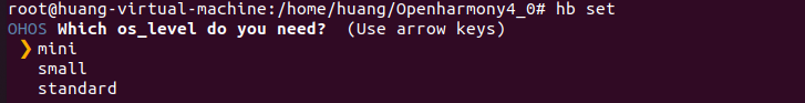
选择mini级系统
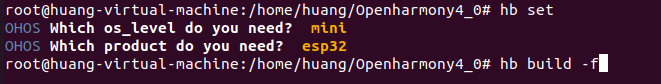
同理 产品选择esp公司下的esp32
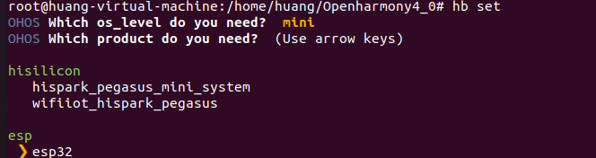
选择完毕后在源码根目录下执行hb build -f 进行编译
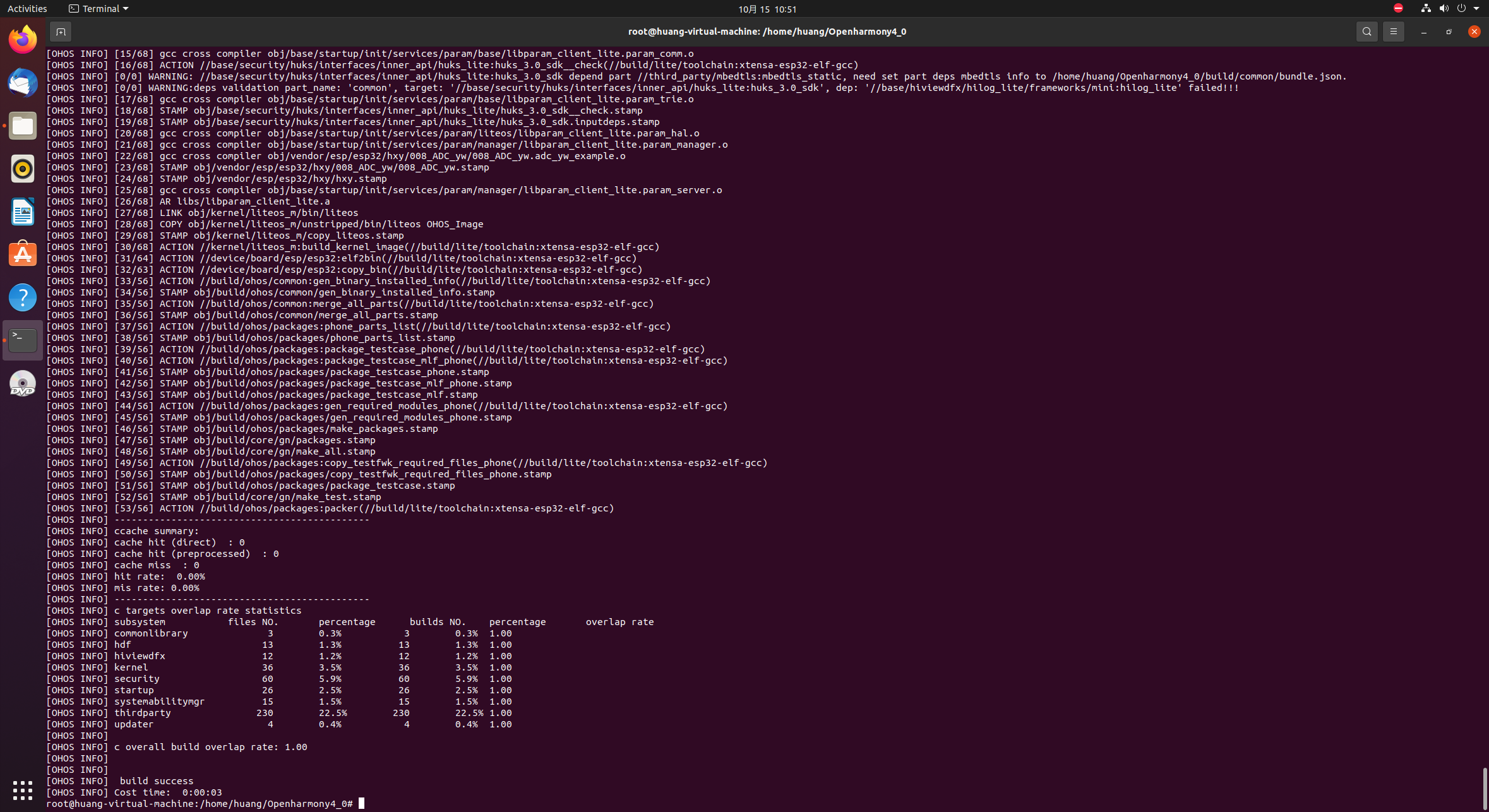
编译完成后会有如下界面,并且编译后的代码固件位于:out\esp32\esp32
实验现象
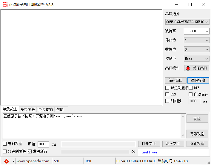
按下ESP32开发板上的EN键,即可观察到实验现象:
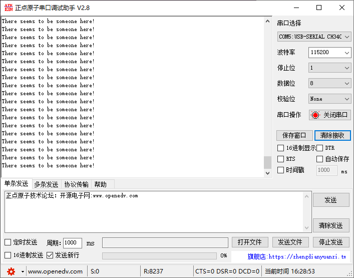
将手掌放置在传感器上方,可以发现传感器成功识别人体并通过串口打印出提示信息,实验成功
本项目代码已上传至gitee:ESP32_Oh: ESP32移植Openharmony
API参考
gpio_config_t 结构体
GPIO初始化结构体
/**
 * @brief Configuration parameters of GPIO pad for gpio_config function
 */
typedef struct {
    uint64_t pin_bit_mask;          /*!< GPIO pin: set with bit mask, each bit maps to a GPIO */
    gpio_mode_t mode;               /*!< GPIO mode: set input/output mode                     */
    gpio_pullup_t pull_up_en;       /*!< GPIO pull-up                                         */
    gpio_pulldown_t pull_down_en;   /*!< GPIO pull-down                                       */
    gpio_int_type_t intr_type;      /*!< GPIO interrupt type                                  */
} gpio_config_t;
gpio_config
GPIO初始化函数
/**
 * @brief GPIO common configuration
 *
 *        Configure GPIO's Mode,pull-up,PullDown,IntrType
 *
 * @param  pGPIOConfig Pointer to GPIO configure struct
 *
 * @return
 *     - ESP_OK success
 *     - ESP_ERR_INVALID_ARG Parameter error
 *
 */
esp_err_t gpio_config(const gpio_config_t *pGPIOConfig);
gpio_reset_pin
将GPIO口默认状态置低
/**
 * @brief Reset an gpio to default state (select gpio function, enable pullup and disable input and output).
 *
 * @param gpio_num GPIO number.
 *
 * @note This function also configures the IOMUX for this pin to the GPIO
 *       function, and disconnects any other peripheral output configured via GPIO
 *       Matrix.
 *
 * @return Always return ESP_OK.
 */
esp_err_t gpio_reset_pin(gpio_num_t gpio_num);
gpio_set_level
设置GPIO口电平状态
/**
 * @brief  GPIO set output level
 *
 * @param  gpio_num GPIO number. If you want to set the output level of e.g. GPIO16, gpio_num should be GPIO_NUM_16 (16);
 * @param  level Output level. 0: low ; 1: high
 *
 * @return
 *     - ESP_OK Success
 *     - ESP_ERR_INVALID_ARG GPIO number error
 *
 */
esp_err_t gpio_set_level(gpio_num_t gpio_num, uint32_t level);
gpio_get_level
获取GPIO口的电平状态
/**
 * @brief  GPIO get input level
 *
 * @warning If the pad is not configured for input (or input and output) the returned value is always 0.
 *
 * @param  gpio_num GPIO number. If you want to get the logic level of e.g. pin GPIO16, gpio_num should be GPIO_NUM_16 (16);
 *
 * @return
 *     - 0 the GPIO input level is 0
 *     - 1 the GPIO input level is 1
 *
 */
int gpio_get_level(gpio_num_t gpio_num);
开源鸿蒙跨平台开发社区汇聚开发者与厂商,共建“一次开发,多端部署”的开源生态,致力于降低跨端开发门槛,推动万物智联创新。
更多推荐


 17
17 0
0- 0


 已为社区贡献4条内容

所有评论(0)